The block casting is made from light aluminium alloy and cored to produce
the water jacket. Cylinder liners are a light press fit into the casting
as are the cast iron valve seats/ports. The key thing in this section is
to get the reference surfaces correct, and ensure all other machining is carried
out accurately from these references.
|
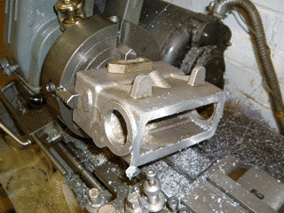
03-Jul-2005: The 4 jaw chuck has enough capacity to hold the
block while the bottom face is machined, providing the first reference
face. |
|
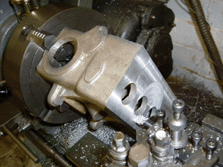
Now the top face can be taken down - it has been left 0.010" higher than
it should be to allow a final skim to be made when the cylinder liners and
valve ports have been pressed in. |
|
Machining the face of the valve chest - this provides another
plane from which a number of other critical dimensions such as bore and valve
positions will be referenced. |
|
And finally the ends of the block to provide a reference plane in the
third axis. |
|
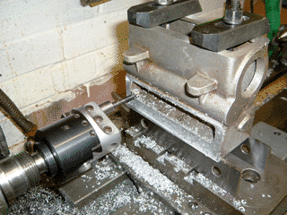
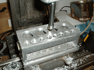
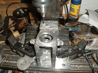
17-Jul-2005: Boring the hole and relief for the liners is being
carried out in the mini-mill; it's easier to line up the bores that way.
The boring operations for the port inserts has already been carried out. |
|
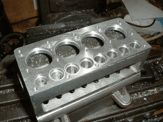
The top deck is done and some coolant transfer holes have been added.
Holes for the studs have been tapped to 4BA (a guess) as the drawings were
not specific on the thread size of the studs. |
|
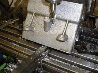
Cheap trick - a half inch of packing has been placed under the base of
the block casting to get the angle right for the dipstick/filler hole. |
|
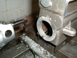
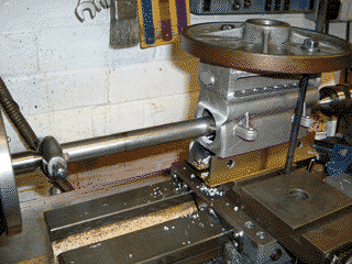
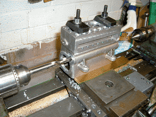
Line boring the recesses for the main bearing retainers. |
|
Back to the milling machine to drill and tap the holes in the front and
rear faces of the block. |
|
Drilling/reaming the bore for the camshaft bearings. |
|
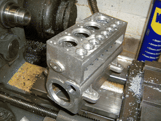
That's the block casting done for now. It will need to have the
side drilled for the ports and manifold retaining studs, although that will
have to wait until the ports are pressed in. |