Duncans Metal Pages
Spindle
Last updated: 30 Nov 2016

Home
Up

The Spindle

The spindle contains the shaft on which the grinding wheels are mounted.  Due to the use of angular contact bearings and a preloading mechanism, there should be no radial or axial play in the spindle over a wide range of temperatures.  Chaddock based this design on one recommended by RHP with some minor changes.

401: Spindle body

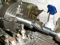
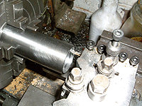
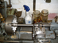
Spindle 26-Dec-06: The spindle is being drilled from both ends to 9/16" initially, these will then be bored out to the correct size.  The stock is 1-3/8" in diameter and has been cleaned up and centred very accurately.  Further checks are carried out after drilling to see if the work has moved in the chuck.
Threading Quite a time consuming job - this is the last bit of threading which is almost the conclusion of 6 hours work to do all the drilling and boring.  Just the tapping for the 2BA countersunk screw to carry out now.

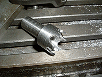
Trepanning tool

Trepan blank 28-Dec-06: Here's the smaller of the two trepanning tools that are needed.  This one will be used to cut the circular slot in the pulley.  A slightly larger trepanning tools is sitting in case hardening compound at 700 degrees C for 4 hours, a first attempt at case hardening. This one is next for the heat treatment...

As a footnote, the 4 hours at 700C in case hardening compound was a waste of time - the part came out softer than the item it was trying to cut.  The second attempt saw 880C (1620F) for 3 hours followed by a straight quench which gave perfect results.

404: Endcaps

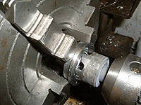
Trepanning 29-Dec-06: This is one of the last tasks on the endcaps, cutting the groove in the face.  The hardened mild steel cutter is working a lot better than I expected.
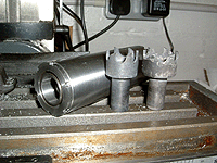
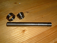
Spindle and cutters The final job is to mill 6 slots in each cap by mounting on a 0.690" arbor and mounting in the dividing head.  I couldn't resist this picture of the spindle, the two cutters look like King and Queen Quorn!

410: Spindle shaft

Spindle 30-Dec-06: Between centres is probably a better way of dealing with this item, but the old Myford is well worn and there's no guarantee of accuracy.  Two short sections were machined to 0.5115" with a relief put between them - it seemed easier to get a short section the same diameter along the length.
Parts The spindle shaft is made from 3 different parts which are glued together.  The outer ring is a very light press onto the inner ring, the inner ring is a tighter press on the spindle.

Assembly

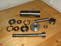
All parts 31-Dec-06: All parts are now made, there's an extra small ring in there to lengthen the spacer as the spring box bottoms out before the spacer tightens.  The pulley does not have a keyway as Delta 88 high strength retainer will be used to affix it to the shaft - once built up, the spindle assembly will not be coming apart.
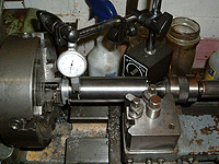
Clocking 01-Jan-07: Holding the spindle by the retaining nut, it's being "clocked" into place.
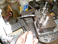
Gauge The toplide is being set over at 20 degrees and I've made a small gauge up to ensure that the angle is repeateable every time I need to make anything for this spindle.
 

These pages are maintained by Duncan Munro.  All content on this site is Copyright ©2002-2025 Duncan Amplification.
Warning: These pages consist of images and descriptions of equipment which can reach high temperatures creating hazardous and potentially dangerous situations.  These pages should not be taken as a step by step guide on how to construct any items or carry out any particular procedure, nor should any references to safety contained herein be taken to guarantee safety in all situations.